
White Paper: Ultra-Long Haul Transmission

Mr. Haack is a member of the investment banking team at First Union that works with optical-networking firms. He recently joined First Union Securities after working in the photonics industry.
Introduction
Forward Error Correction
Raman Amplification
Dispersion Management
Soliton Techniques
Ultra-Long Haul Transmission Today
Introduction
In optical fiber communications, the optical pulse will lose its shape and need to be electronically re-generated about every 600 km. Therefore, in most long-haul systems, the optical pulse is decoded electronically every 600 km (by a photoreceiver), then it is retimed electronically, and then re-transmitted by a laser. Thus, as with grammar school, the 3 R's are still a requirement--in this case the 3 R's of optical communications are retiming, reshaping, regeneration.1 Fiber-optic telecommunications networks have been built in this manner, historically; however, having an electronic node every 600 km is unnecessary and in recent years there has been renewed interest about truly all-optical network backbones, or ultra-long haul transmission. There are several techniques that enable ultra-long haul transmission: Forward Error Correction, Raman amplification, and dispersion management schemes.
Forward Error Correction
In data communications, the data is sent as a packet, a series of 1's and 0's represent the data in a digital format. This packet is sent down the transmission line to the next node on the system. Sometimes, there are errors in the transmission. Historically, most telecommunications systems employed schemes where if there was an error at the receiving end, the receiver sent a signal to the transmitter and the packet was resent by the transmitter. Forward Error Correction (FEC) was relegated to communications applications outside of telecom where distance truly mattered--say, in satellite communications.
The advent of ultra-long haul telecommunications systems gives a smaller margin of error for error correction techniques. The longer distances mean that errors can "pile up", causing the system to get clogged. So, Forward Error Correction techniques alleviate this problem somewhat, as errors are addressed immediately at the receiver end.
Raman Amplification
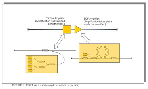
In ultra-long-haul transmission, Raman amplification is often used in conjunction with or in lieu of traditional EDFAs to help control the introduction of noise into the system. A Raman amplifier might be used as a pre-amp before an EDFA; in this scheme, the additional power boost by the Raman amplifier varies by fiber type and fiber age--an approximation of this boost would be 30% (the actual amount will vary quite a bit as it depends on fiber type and fiber age). Raman amplification takes place along the fiber itself, the amplification going backwards along the network, for about 20 km or so. The reason that Raman amplification is used is that it maintains the signal-to-noise ratio better than EDFAs.
Raman Amplification can help enable a faster data rate instead of longer transmission distances; however, to enable ultra-long haul transmission the most interesting facet of Raman amplification is option 3), below:
1) Same data rate, increase spacing between repeater stations from 100 km to, say, 140 km.
2) Same spacing between repeaters, faster data rate.
3) Same data rate, same spacing between repeaters, longer distance between electrical regeneration.
While Raman amplification aids the ultra-long haul system by aiding in controlling for noise, the problem of dispersion must be dealt with.
Dispersion Management
While Raman amplification speaks to the improving loss of power without introducing so much noise, the major problem in ultra-long haul transmission is that the optical pulse will lose its shape (Figure 2).
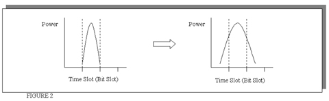
Remember that in telecommunications, data is represented by a string of 1's and 0's, or an ON and an OFF signal. An expansion of the optical pulse is a bad thing--the receiver is unable to distinguish whether there is an ON or an OFF signal; for instance, as shown above, the ON pulse expanded into the OFF time slot. There is such a thing as a special fiber where there is minimal dispersion, however, such a scheme will only work for the center wavelength and the other channels will still suffer this effect--the dispersion is not constant across all wavelengths.
A standard optical pulse will suffer distortions in not only the time domain but in the frequency domain as well. Frequency is simply another way of saying wavelength:
(frequency of light) = (speed of light in vacuum) / (wavelength)
Note that for a 1550 nm signal, the frequency of light is 193.4 THz, the corresponding wavelength is 1550 nm, and if you are transmitting with a data rate of 10 Gb/s, the modulation frequency (amplitude modulation) will be 10 GHz. Through a method known as Fourier transforms (the mathematics of which is fairly complex), the pulse in the time domain relates to the pulse in the frequency domain. Thus, over a long distance, the optical pulse will lose it's shape in both the frequency domain and in the time domain. This means that at the receiver, in the time domain, the bits will have spread into the adjacent bit slots. If this happens, the receiver is unable to distinguish between the bits. (Figure 3).
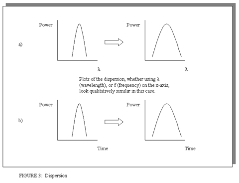
As drawn above, each optical pulse, centred about a specific frequency, still has different frequency components that will be distorted, this is known as chromatic dispersion (different frequencies within a single pulse will travel through the fiber at different speeds and thus the pulse broadens). At 1550 nm (193.4 THz), the dispersion is about 20 ps/nm km for SMF fiber, a few ps/nm km for NZ-DSF fiber, and almost zero for DSF fiber.2 Most carriers are using either SMF or NZ-DSF fiber in their networks.3 Besides chromatic dispersion, Polarization Mode Dispersion, arising from asymmetries in the fiber or from asymmetries in components such as a MUX/DEMUX, causes a similar effect as chromatic dispersion.
To combat the effects of dispersion, designers must use a dispersion management scheme. This can be accomplished by a variety of methods using filtering and other techniques. While distances can be extended by "passive" techniques involving special fibers or some type of dispersion compensating module, perhaps the best method to combat dispersion is to utilize a soliton transmission scheme.
Soliton Techniques
Recent commercial developments point to the possibility of commercial soliton transmission systems. Soliton transmission in telecommunications has been a project in the research lab for many years. Early pioneers were Linn Mollenauer of Lucent Technologies (one experiment goes back to 1980--he's honored in the little Lucent museum at the headquarters) and Akira Hasegawa of KDD, who first published a paper on this subject in 1973.4 Basically, a soliton is a special version of an optical light pulse where the pulse maintains its shape over much greater distances than an ordinary optical pulse--this enables ultra-long haul communications.

Solitons are a phenomenon that relate not only to lightwaves, but to other types of waves as well. Solitons were first discovered in Scotland in 1834 by J.S. Russell, when he observed the freak occurrence of a soliton water wave:
I was observing the motion of a boat which was rapidly drawn along a narrow channel by a pair of horses when the boat suddenly stopped; not so the mass of water in the channel which it had put in motion: it accumulated around the prow of the vessel in a state of great agitation, then suddenly leaving it behind, rolled forward with great velocity, assuming the form of a large solitary elevation, a rounded smooth and well defined heap of water, which continued its course along the channel apparently without diminution of speed. I followed it on horseback [for nearly 6 miles], and overtook it still rolling on at a rate of some eight or nine miles an hour, preserving its original figure some thirty feet long and a foot or foot and a half in height.
Just like the special bow wave that J.S. Russell observed back in 1834, a "special" optical pulse is needed that maintains its shape as it transmits through an optical fiber. This is done by a special transmission technique known as a soliton transmission. A soliton is a special shape of a wave that balances two competing physics effects to maintain its shape. A soliton is a phenomenon of physics that can be seen in water, optical fiber, and other mediums. (Figure 5).
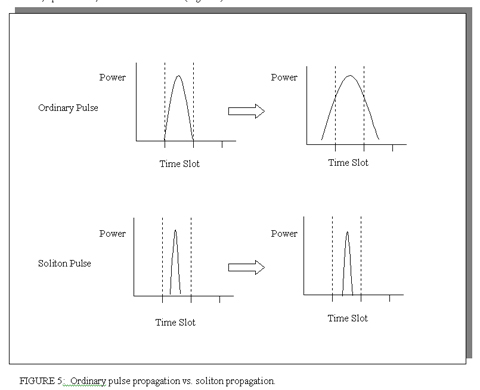
Not only is the pulse shaped in the frequency domain, but it also will compress in the time domain as well. Once the "special" soliton pulse is generated, it will compress in shape until it stabilizes--in this shape it will then hold it's waveform in the time domain as well. Without soliton pulses, different frequencies of the wave will travel at different speeds through the fiber, and "leak" into the adjacent bit slot. With solitons, at the optical receiver, the bit stream is maintained and the optical pulses are in the correct bit slot.
The construction of the soliton pulse is achieved through correctly taking into account several issues in optical physics.
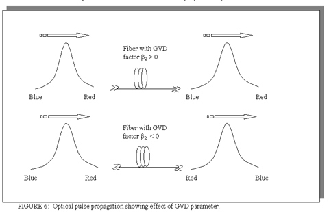
In fiber optics, interplay between two phenomenon of a branch of physics known as non-linear optics can lead to soliton propagation. One of these factors is group velocity dispersion (GVD). Wave propagation in optical fiber is governed by a mathematical equation derived by high-level physics, from which the GVD can be arrived at--GVD is in turn significantly influenced by a parameter, b2; whether the pulse will narrow or broaden depends on the sign of this parameter. (See Figure 6). The other effect which counterbalances the GVD to enable soliton propagation is the Kerr effect. (To be precise, the self-phase modulation (SPM) is actually what counterbalances the GVD to create the soliton--the Kerr effect is responsible for SPM.) The Kerr effect is a nonlinear phenomenon that increases the index of refraction of the fiber proportional to the intensity of the light pulse. When an optical pulse is transmitted through a fiber, normally, the group velocity dispersion factor (GVD) is positive and the longer wavelength "red components" of an optical pulse travel faster that the shorter wavelength "blue components" as shown in figure 6.6 This gives rise to chromatic dispersion (See Figure 3a). When the GVD is negative, the situation is reversed and the shorter wavelength "blue components" travel faster than the longer wavelength "red components". (Figure 6) It is the latter situation that gives rise to solitons when balanced by a positive optical Kerr effect.
Early soliton schemes, or "classic" solitons, usually required the use of a special fiber and were oriented towards single-channel systems. The market acceptance of DWDM, with channels at different wavelengths sharing the same fiber, ended any chance of commercial development of a classic soliton based network. Over the last half-decade, there has been significant progress on a new technique, known as dispersion-managed solitons. Historically, soliton transmission schemes required the use of special optical fibers that were made with an anomalous GVD; however, dispersion-managed solitons can be used with standard fiber that has normal GVD's as long as the GVD is kept in the appropriate region.7 With dispersion-managed solitons, greenfield networks do not need to be built to support a soliton-based transmission architecture, and the installed fiber plant can be utilized.
A dispersion-managed soliton system would not require a special fiber; also, the dispersion-managed soliton can be created with a standard DFB laser and lithium-niobate modulator. The modulator is driven differently (sinusoidally) than it is for traditional transmission, at about half the bit-rate. This scheme will give a pulse that is an extremely good approximation of a dispersion-managed soliton and will be about one-third the width of a normal bit. (There are also other methods of soliton pulse creation.8)
Revisiting the Raman amplification discussed earlier, solitons benefit from such amplification. Given that the propagation of the pulse must be closely controlled lest the soliton not conform to soliton physics, noise must be controlled and amplifier stations will need to be closer together, (or a combined scheme of Raman and EDFAs must be used). Besides the noise effect discussed earlier, soliton systems are affected by amplifier noise that can introduce timing jitter, known as the Gordon-Haus effect.9 Because it doesn't have the level of ASE noise that EDFAs have, Raman amplification is often used in soliton transmission today. EDFAs can be used, however, the noise issue must be addressed in some fashion. Thus, Raman amplification enables a soliton network to be built with reasonable amplifier station distances and helps control the timing jitter.
Ultra-Long Haul Transmission Today
As mentioned above, early pioneers in the field of ultra-long haul transmission were AT&T as well as KDD of Japan. Their initial focus was on undersea communication, an obvious situation where ultra-long haul communication makes sense. It is no doubt that this effort continues at Lucent, Tyco, and KDD. In the last two years, several firms have sprung up which are touting ultra-long haul communications for terrestrial networks; it is likely that at least Corvis is at least working on soliton transmission schemes. In 1998, a few companies began to surface that were founded to commercialize ultra-long haul communications: Qtera (purchased by Nortel last year), Algety (purchased by Corvis), and Corvis. While only Algety Telecom has publicly stated that the firm is working on soliton transmission systems, it is certainly possible that a major thrust for Qtera and Corvis may be a soliton transmission scheme. Qtera opened the office in Richardson in order to hire senior systems architect Niall Robinson of MCI; while at MCI, Niall had done work with Pirelli on soliton transmission.10 (Now that Cisco has acquired these assets of Pirelli, it is no doubt that Cisco has some capability in soliton transmission).
While Forward Error Correction, Raman amplification, dispersion management, and soliton transmission schemes have been around for some time, as with DWDM, credit again must be given to Dr. Huber, for just as DWDM wasn't invented at Ciena, ultra-long haul transmission wasn't invented at Corvis. In both cases credit is due to Dr. Huber for developing the commercial potential of ultra-long haul technology and pushing the frontiers of what is available commercially.
NZ-DSF: Non-Zero, Dispersion-Shifted Fiber.
DCF: Dispersion Compensating Fiber.
FEC: Forward Error Correction scheme.
FOOTNOTES
1. R. Ramaswami, K. Sivarajan, Optical Networks, Morgan Kaufmann Publishers, Inc., 1998, p. 340.
2. K. Richards, "Bandwidth Without Borders", Fiber Exchange, March 25, 2000, pp. 10-11.
3. T. Georges, J. Faul, "Soliton Transport Gives Backbone More Speed", FibreSystems International, June 2000, pp. 51-54.
4. G. Agrawal, Nonlinear Fiber Optics, Academic Press, 1989, p. 148.
5. M. Remoissenet, Waves Called Solitons, Springer, 1996.
6. Agrawal, op cit, p. 66.
7. M. Nakazawa, H. Kubota, K. Suzuki, E. Yamada, and A. Sahara, "Ultrahigh-Speed Long-Distance TDM and WDM Soliton Transmission Technologies, IEEE Journal of Selected Topics in Quantum Electronics, March/April 2000, pp. 363-4.
8. D. Jones, S. Namiki, D. Barbier, E. Ippen, H. Haus, "116-fs Soliton Source Based on an Er-Yb Codoped Waveguide Amplifier", IEEE Photonics Technology Letters, May 1998, pp. 666-668.
9. Agrawal, op cit, p. 177.
10. N. Robinson, "Solitons to Lower Cost of Long-Haul Transmission", www.fiberopticsonline.com, July 17, 1998.
11. OFC Technical Journal, 1998.
12. H. Taga, M. Suzuki, N. Edagawa, S. Yamamoto, S. Akiba, "Long-Distance WDM Transmission Experiments Using the Dispersion Slope Compensator", IEEE Journal of Quantum Electronics, November 1998, p. 2055 - 2063.
13. F. Matera, M. Settembre, M. Tamburrini, F. Favre, D. Le Guen, T. Georges, M. Henry, G. Michaud, P. Franco, A. Schiffini, M. Romagnoli, M. Guglielmucci, and Sergio Cascelli, "Field Demonstration of 40 Gb/s Soliton Transmission with Alternate Polarizations, Journal of Lightwave Technology, November 1999, pp. 2225 - 2234.
14. H. Debregeas-Sillard, P. Doussiere, A. Bodere, P. Rael, O. Legouezigou, G. Michaud, F. Gaborit, S. Gauchard, and F. Brillouet, "New WDM Optimized Integrated Laser-Electroabsorption Modulator for 1000-km 2.5-Gb/s Transmission Over a Wide Range of Operating Conditions", IEEE Photonics Technology Letters, November 1999, pp. 1485-1487.
15. M. Nakazawa et al, op cit, pp. 363-396.
16. ECOC, PD2-2, 1999.
17. A. Gnauck, L. Garrett, Y. Danziger, U. Levy, and M. Tur, "Dispersion and Dispersion-Slope Compensation of NZDSF for 40-Gb/s Operation over the Entire C Band", www.lasercomm-inc.com, white paper.
18. NA
19. Qtera (Nortel) press release dated March 7, 2000.
20. Corvis press release dated August 21, 2000.
21. P. Rigby, "Bell Labs Boosts Soliton Stamina", FibreSystems International, August/September 2000, p. 15.
22. Sycamore press release dated September 27, 2000.
23. J. Zyskind, G. Pendock, M. Cahill, G. Bartolini, J. Ranka, S. Park, "High Capacity, Ultra-Long Haul Transmission", NFOEC 2000 Technical Proceedings, pp. 342-350.
ADDITIONAL RESOURCES
24. I. Morita, M. Suzuki, N. Edagawa, K. Tanaka, and S. Yamamoto, "Long-Haul Soliton WDM Transmission with Periodic Dispersion Compensation and Dispersion Slope Compensation", Journal of Lightwave Technology, January 1999, pp. 80-85.
25. B. Saleh, M. Teich, Fundamentals of Photonics, John Wiley & Sons, 1991.
26. Grigoryan et al, "Using Color to Understand Light Transmission", Optics and Photonics News, August 2000.
27. A. Hasegawa, "An Historical Review of Applications of Optical Solitons for High Speed Communications, Chaos, September 2000, pp. 475-485.