Photonics Simulation Eases Design and Protects Intellectual Property

By: Arthur Lowery, N/A
Contents
Common language
Customer-vendor boundaries
Documenting the design process
Protecting the value of a company
Capacity expansion
While exhibiting photonics simulation tools at OFC '97, Virtual Photonics executives were often asked, "Why simulate?" In those days, a designer could sketch an optical communications system on the back of an envelope, except for the longest of long-haul systems. Electronics neatly divided a system into spans, each of which could be conservatively designed.
In 1999, capacity demands are pushing photonic system design beyond conservative design rules and standards. Optical networks put 'old' analog design problems back on the drawing board. Engineers are developing photonic circuits for wavelength conversion, regeneration, and demultiplexing. Instead of asking, "Why simulate," the question now becomes, "Which simulator?"
Engineers face new and compelling reasons to simulate a photonic system. These updated reasons go beyond the obvious benefit of rapid system design. The immediate advantages of photonic simulation include testing ideas and verifying designs, parameters, and upgrades. But simulation also captures a design process and allows effective and accurate communication of this process to fellow teams, customers or vendors, wherever or whoever they may be.
Once accepted, the language of simulation provides a basis for future enhancements, design upgrades and legal arguments. The simulation itself becomes a check on the accuracy of communication. It can be distributed, archived, capitalized upon, discussed, and even rejected. It can form the basis of revised parameters and specifications.
Common language
Despite the best intentions of engineers writing unambiguous technical specifications or engineering proposals, system design requires from a common language. A recent event in outer space has shown that simple misunderstandings can wreck the most carefully of planned projects. The Mars Climate Orbiter, which became a very expensive plough because of a metric-imperial measurements mix-up, reminds us that units of measurement are as important as the values themselves. Because transoceanic fiber optic communications systems are at least twice as expensive as the Mars Orbiter, and the systems are almost impossible to upgrade mid-span after installation, photonics engineers should be equally as careful to check measurements and specifications.
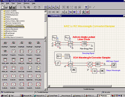
A shared photonic simulation platform gives engineers a de facto language and the ability to check a supplier's system or a customer's design on a standard platform. Transmission design software simulates the performance of components, circuits, systems and networks using optimized signal representations (see Fig. 1).

Years of research and expert input go into the software. Laser model parameters for Virtual Photonics' Photonic Transmission Design suite, for instance, were developed by a 30-strong group of researchers in the European Union, over a series of meetings and a host of emails. Although the definitions cannot please everybody, the definitions comprise a well-defined standard, and the meetings have highlighted how designers must write the definitions in order to avoid misconceptions. The definition of the position of facets with respect to the grating in a DFB laser, for instance, requires six basic definitions.
Customer-vendor boundaries
Groups can easily share system models from the design software. A customer or vendor can import the models into its simulator in a matter of seconds. This allows design teams to pass rich information over company and team boundaries, much richer than the information that appears on the data sheet of an individual component. Simulating on both sides of a communication boundary provides a worthwhile check on the effectiveness of the communication. Designers may find, for instance, a requested operation may not produce the expected results.
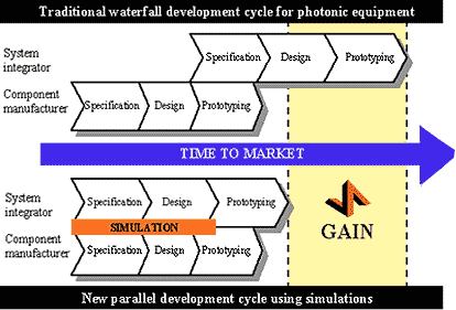
Sharing rich information between design teams reduces the design cycle time considerably (see Fig. 2). Systems integrators and equipment manufacturers need not wait until the release of a component—they can use a simulation of the component as an indication of its expected performance. Simulations can be exchanged in minutes, and queries dealt with in hours. Designers can include uncertainties in the component specification by using swept or randomly-distributed parameter values. The simulator mandates a communications language.

Even if the designer does not like the definitions set down by the simulator, at least the simulator allows engineers to check revised definitions. Engineers can enter parameters into the design tool as expressions. The parameter 3e8/wavelength, for instance, can convert wavelength to frequency. Designers can check the revised definition using the converted parameters, and compare results by comparing simulation output files.
Documenting the design process
Capturing a design within a simulation produces a record of the design process. Because each topology only requires a few kilobytes to record its structure and parameters, recording its progress is easy. Sending the evolving designs, such as on a disk, to an independent third party to be registered by a lawyer easily creates a trail of invention.
The invention record is irrefutable evidence in the case of a patent dispute, but places little overhead on the design process, apart from comments placed on the schematic on the rational of the design. Checking the design process is also invaluable when locating errors. Correcting them at the right point in the process will ensure that they will not occur again: correcting them at the wrong point will allow future errors.
Protecting the value of a company
Simulating photonic systems used to be an in-house exercise. An expert in the company would write code, and to run the code when called upon. Sometimes the expert would pass on the code to other researchers, who would ask the originator for help and support. This process relies on the longevity of the expert, and his or her willingness to continue to support the software. Part of risk management is to make the success of a company independent of an individual.
More important than protecting the value of a simulator is protecting the designs and expertise of a company. Encouraging the use of a simulation platform to record design evolutions and component parameters captures this expertise in a form easily read by third parties—in some cases, merging companies and joint-project teams.
Capacity expansion
Simulation makes the interplay of new technologies to expand network capacity manageable. Dense wavelength division multiplexing (DWDM) systems increase capacity by using existing capacity, but the modulation efficiency in bits/Hz is nowhere near that of microwave systems, partially due to the low signal-to-noise ratios in optical systems. Recent capacity advances arise from widening the amplification bandwidth in systems with dual-band EDFAs, for example. Future advances are likely to come from using this bandwidth more efficiently by increasing the channel rates and decreasing the channel spacing.
Experts often argue about which technology will provide larger bandwidths for communications, but several technologies will contribute something to increasing bandwidth. Technology proponents will push a particular strategy, but in the long run, advances will be based on a prudent combination of the technologies. To wit:
- DWDM will use more wavelengths and multi-band amplifiers, and merge-window fibers will expand available optical bandwidth;
- modulation schemes will contribute increased spectral efficiency;
- error correction coding will compensate for noise and channel impairments;
- mixed analog-digital systems will provide services obeying regulatory restrictions;
- tunable sources will provide back up transmitters and possibly wavelength switching;
- wavelength converters will expand the flexibility of networks and provide contention-resolving capabilities in packet-switched networks;
- 2R and 3R regenerators will allow longer reach in essentially analog networks;
- optical switching will provide millisecond switching for IP networks, or ns switching for ATM networks;
- a mix of electronics and optics will provide multi-gigabit optical access.
All of these technologies require some appreciation, especially when combined. Simulation is the ideal tool to explore the interactions, to study the use of photonic circuits as part of wider systems concepts, and to assess new technologies by dropping them into simulations of existing systems.
About the author:
Arthur Lowery is chief technology officer for Virtual Photonics Inc. He can be reached at a.lowery@virtualphotonics.com.
