Optical Fiber Cabling for Gigabit Ethernet Applications
By: Allen Dixon, Martyn Easton, and Herb Congdon, Corning Cable Systems
Contents
Forging standards for Gigabit Ethernet
Starting with gigabit applications
What is so different about Gigabit Ethernet?
Why are lasers required?
What are the issues of using a laser with multimode fiber?
Dealing with differential mode delay
Conditioning the launch externally
What is the maximum length for a Gigabit Ethernet system?
Are the power budgets still important?
Why not just use LX exclusively?
Considerations with new cabling
Never underestimate the power of an installed base. Gigabit Ethernet (GbE) is a natural extension of the Ethernet already used in more than 80 million desktops. This is the primary reason that the new protocol will prove to be widely deployed.
Forging standards for Gigabit Ethernet
Riding the wave of success of 10 Mbps Ethernet and 100 Mbps Fast Ethernet, the networking community sees a big opportunity for GbE as a transmission protocol able to handle escalating bandwidth needs on users' networks. A necessary first step has been to forge interoperability specifications to allow the creation of compatible products in a multivendor environment.
The Institute of Electrical and Electronics Engineers adopted the new work item as IEEE 802.3z with a fast track to produce the optical fiber specification for GbE. The intent was to quickly complete a specification that defined requirements to bring standardized electronics components to market. This process has also required the definition of the optical fiber cabling required to carry the gigabit transmissions.
Starting with gigabit applications
The primary applications for the GbE protocol are expected to be very high-speed backbone connections, large pipe access to servers, and other natural bandwidth bottlenecks in the network architecture. These applications begin to define the scope of the physical cable plant involved. To enable the early adoption of the technology, the standards committee wished to forge specifications enabled operation over existing optical fiber cabling as well as define cabling needs for new installations.
The GbE standardization and specification process uncovered some technical issues that required pioneering work to investigate and characterize the interaction between the light sources and optical fibers to ensure successful system operation.
What is so different about Gigabit Ethernet?
GbE defines an application capable of transmitting and receiving over one gigabit of information in one second. The unique requirements of this high a data rate require laser sources instead of light emitting diodes (LEDs). Accordingly, GbE is the first large-scale application using lasers, instead of light emitting diodes (LEDs), to launch light signals into multimode optical fiber.
Why are lasers required?
Lasers can operate at data rates much higher than LEDs. LEDs can operate up to 622 million bits (ons or offs) per second. Faster data rates require lasers because the rise and fall times (the time it takes for a laser to turn completely on and completely off) are much faster than for LEDs, allowing for tighter spacing of light pulses. Lasers are required, and are commonly used, for very high data rate, long haul single-mode fiber applications.
However, lasers are considerably more expensive than LEDs. Fortunately, a new technology in lasers, called the VCSEL (Vertical Cavity Surface Emitting Laser) has been developed. VCSELs provide a laser quality source at a similar manufacturing cost of an LED. This means a transmitter using a VCSEL can be much less expensive than a typical laser transmitter. VCSELs, however, are currently commercially available only at the 850 nm wavelength.
Although lasers are used, single-mode fiber is not required? GbE is specified to operate over either multimode fiber or single-mode fiber. However, there are some special considerations for multimode fiber when using laser sources operating at GbE data rates.
What are the issues of using a laser with multimode fiber?
The commonly used LEDs launch a wide pattern of light—wider than the core diameter—overfilling the fiber core (see Figure 1). Laser light fills only a portion of the core due to the smaller, focused light pattern that lasers emit.
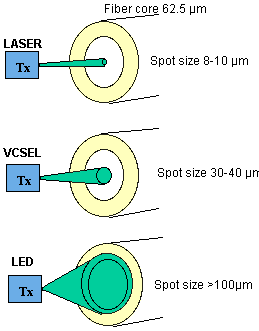
Initially, common sense reasoned that the bandwidth of a multimode fiber would increase using laser launches. Since the complete core is not filled with light by the source, all the modes are not filled, there would be less modal dispersion and a consequential increase in the amount of information that could be sent down the fiber. However, system testing showed this is not always the case.
When laser light is launched into the center of some multimode fibers, more than one group of modes can be excited due to a centerline "dip" in the index of refraction profile of the fiber (see Figure 2). When a laser is launched into this dip, which results from the fiber manufacturing process, multiple signals can be created that overlap each other—the receiver may not be able to accurately demodulate the signal.
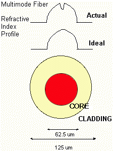
This phenomenon is called DMD (differential mode delay). DMD effects can occur with both traditional laser sources as well as with the newer VCSELs. So, instead of getting more bandwidth from a restricted, or under-filled, laser launch, in some cases the bandwidth of a fiber is actually reduced when a laser is used. To account for these potential lower bandwidth conditions, the maximum operating link lengths for gigabit speeds have to be shortened.
Dealing with differential mode delay
Simply increasing the fiber's LED bandwidth is not a reliable solution as that does not change the centerline interactions causing the problem. Controlling the refractive index profile along the entire length of the fiber during the fiber manufacturing process will mitigate the phenomenon, but can be of no help for existing fiber installations.
Using today's fibers and existing installations, the way to overcome DMD effects is by precisely controlling the laser launch position into the core of a multimode fiber. The launch is shaped and positioned so that the light is offset from the center of the fiber core, minimizing the effects of the centerline "dip."
There are two types of transmitters used for GbE operation: SX, or short wave (850 nm), and LX, or long wave (1300 nm). The SX transmitters can be conditioned internally to provide the offset once the fiber is connected. LX transmitters, however, will have to work for both single-mode and multimode fibers.
Conditioning the launch externally
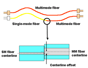
If the offset launch is conditioned internally, the LX transmitters will not work successfully with single-mode fiber, which cannot tolerate this offset due to the smaller core size. Therefore, LX multimode launches have to be conditioned externally. This can be achieved simply by connecting the GbE electronics to the cable plant using a special patch cord called a "Mode Conditioning Patch Cord."
This special patch cord contains a single-mode fiber (for attaching to the transmitter) connected precisely off-center to a multimode fiber (see Figure 3). This offset creates a launch that performs very well on multimode fiber. The GbE specification requires the offset launch positioning for LX 1300 nm longwave systems operating on 62.5 or 50 µ multimode fiber.
What is the maximum length for a Gigabit Ethernet system?
The maximum reach will depend on several factors, most importantly the operating wavelength of the system, the fiber type, and bandwidth. Tables 1 and 2 summarize the lengths which the draft GbE specifications will support. The use of the offset launch positioning is assumed for these tables.
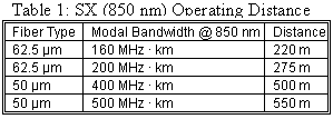

Bear in mind that these specifications represent the worst case parameters for all of the system components.
Are the power budgets still important?
The considerations above and resulting link operating distances are concerned with the modal dispersion across a link. The link loss, or attenuation, is different than the modal dispersion, but is still very important. In fact, both the dispersion and attenuation combine together to limit the effective transmission distance. In addition to the maximum operating distances, the IEEE specifications also detail the maximum loss allowed across a link, or power budget.
The significant contributors to loss are the attenuation due to the length of cable, and the losses across connectors and/or splices. Other losses can occur due to sharp bends in the cables, but these should not be significant if the correct installation techniques are used and the minimum recommended cable bend radius is not exceeded.
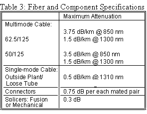
Once an optical fiber cable link is installed, the link loss is quickly and easily measured with a calibrated light source and power meter. But for planning purposes the specifications in Table 3 can be used (these are worst case attenuation values allowed for the cabling components):
Tables 4 and 5 include the available power budget in addition to the maximum link distance. Then, assuming this maximum link distance, the maximum cable attenuation is calculated and is used to determine the power margin.
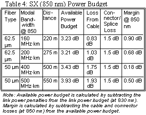
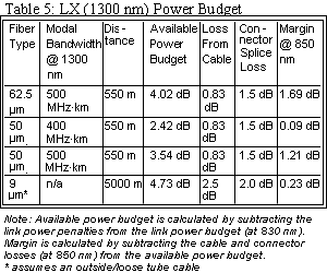
The larger power margins common to most optical fiber applications are now much smaller, less than 1 dB in most cases. The optical loss of mated multimode connector pairs for laser-like sources is expected to be lower than for LED sources, but is currently not specified. However, allowing 0.75 dB per connector is a good, conservative value to use for planning purposes. At some point in the near future, it may be possible to apply a different loss value for SX system connector loss.
Why not just use LX exclusively?
The cost is usually prohibitive. While the LX specification is more powerful, offering significantly longer link lengths, it is also significantly more expensive than the SX specification. The cost delta is due to the optics needed for the electronics. As previously mentioned, the single-mode lasers needed for LX transmitters are much more expensive than the VCSELs which can be used for SX transmitters. Currently, VCSEL technology is only available at 850 nm, while 1300 nm devices are being developed.
If you are planning to run GbE speeds then you need to first address two questions: 1) What is the application or segment of my network being upgraded and what is its link length?; 2) Do I have an existing optical fiber cable plant or will I need to install new optical fiber cabling?
Existing optical fiber cabling is most likely to contain the industry standard 160/500 MHz·km 62.5/125 multimode fiber and maybe some single-mode fibers. Comparing the actual link lengths and link losses to the tables above will determine whether an SX or an LX electronics solution is required. Server connections to network switches or hubs are usually shorter link lengths and will likely only require the less expensive SX solution.
Considerations with new cabling
If you will be installing new optical fiber cabling, a number of factors should be considered. Cabling is an infrastructure investment for the fundamental reason that it is difficult and/or expensive to replace. As such, it will be required to support multiple applications over its useful life.
Considering the planned link lengths and budgeted link losses, the cabling choice must provide compatibility with current lower speed applications as well as support future growth to faster applications even beyond GbE. As well, factors such as fiber identification, cable administration, patch cord management, standards compatibility, industry support, price, and availability should be taken into account.
For backbone applications it is recommended to consider hybrid cables, cables containing both multimode and single-mode fibers. The multimode fiber will provide the capacity you need now. These should be 62.5/125 µm with 200/500 MHz·km "LED" bandwidth and, ideally, also carry a vendor assurance for laser-based applications. The single-mode fiber allows for future expansion of the data rate capabilities.
For horizontal cabling and server connections, distances are typically less than 100 meters. For these shorter links, 62.5/125 µm multimode fiber provides plenty of bandwidth to meet current and future needs.
Siecor specializes in the development, manufacture, and marketing of fiber optic cables, ancillary hardware, connectors, splicing, and test equipment, and specialized copper telephone accessories for voice, data, and video communications applications.
