
Neatness Counts: Unique and Flexible Housing Options For Fiber Optic Datacom/Voice Installation
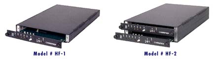
VERSITRON FOM II enclosures are available in high-density, rack-mount configurations or as stand-alone desk-top packages. The HF-1 desk-top enclosure provides a slide-in chassis for one FOM II modem circuit card while the HF-2 provides a slide-in chassis for two FOM II cards. These enclosures are light-weight, have rubber feet, and therefore may be placed in a variety of locations or stacked. The modem circuit cards have two screws on their front panel to hold the device in the enclosure. The digital, fiber and power interfaces are accessible from the rear of the enclosure for your convenience. Power may be provided to each individual modem circuit card in any enclosure or via a single or dual redundant power supply in the high-density rack-mount chassis.
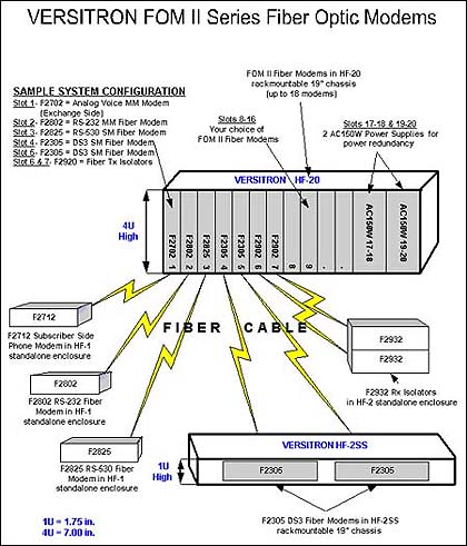
 If rack space is a problem, the HF-2SS Space Saver Chassis comes to the rescue. This chassis fits into a standard 19" equipment rack, and offers a horizontal side-by-side installation of either 1 or 2 FOM II modem circuit cards. The height of this chassis is only one "rack unit." In those applications where only 1 or 2 fiber optic links must be installed in a small space, the HF-2SS is ideal. For ease of installation, all connections are made from the rear of the chassis.
 For applications requiring many fiber optic links, the HF-20 chassis fills the bill. This chassis fits in a standard 19" equipment rack and permits vertical placement of up to 20 FOM II modem circuit cards. There are no committed slots, and modems can operate with individual or chassis power supplies. The Model AC150W power supply/system monitor provides single or redundant power to the HF-20 chassis.
 The use of the Model AC150W power supply/system monitor provides the following installation options. This model is 2 slots wide. One HF-20 holds 18 modems with 1 AC150W installed, or 16 modems with 2 AC150Ws installed. The Model AC150W has an output power of 200 watts to handle the demands of a full set of modems. The power supply/system monitor incorporates circuitry that allows for the addition of redundant power supply by simply inserting a second unit into the HF-20 chassis. Both the chassis and the FOM II modem circuit cards have power regulators to tolerate supply voltage variation and minimize heat generation.
In addition, each AC150W's alarm circuit monitors its own output voltage as well as the common alarm circuit for each FOM II Series modem. The monitor circuit control indicators are located in the power supply front panel and relay contacts for the external alarm in the rear.
If you have chosen a single or dual card enclosure, power supply models PSAC08 and PSAC09 are used. These power supplies are wall mount AC/DC transformers. The PSAC08 is 110VAC, USA style plug. The PSAC09 is 220 VAC with a European style plug. Any of the FOM II circuit cards are compatible with either of these power supplies.
Accomodating a variety of installation requirements and configurations is not a problem when choosing VERSITRON products. Side by side, stackable, or stand-alone/desktop options within a framework of various "powering up" styles should adequately address any of your "housing" needs.
Source: VERSITRON