Compact, High Efficiency Mux/Demux Adds Flexibility to Singlemode and Multi-mode DWDM Systems
By: Tim Boord and Terry VanderWert, APA Optics, Inc. Inc.
Contents
Design goals
High-frequency gratings
Optical design and packaging
Performance
Platform design
The drive for both higher bandwidth, and greater flexibility in managing this bandwidth are key factors in the design of today's fiber optic networks. Requirements for dense wavelength division multiplexing (DWDM) multiplexer/demultiplexer (mux/demux) components are evolving to meet these demands. Several major changes affect the requirements and the design of WDM passive components:
- demand for higher bandwidth is driving the need for narrower channel (wavelength) spacing and higher channel counts. Typical channel spacings are now 1.6 nm (200 GHz), 0.8 nm (100 GHz), and 0.4 nm (50 GHz), in devices with channel counts of 16 or higher;
- increasing use of fiber optics LAN, campus, and metro networks drives the need for improved throughput—essentially reduced insertion loss—as a means of reducing amplification costs. This prompts the increased use of DWDM in both existing and new installations of multi-mode fiber; and
- greater need, triggered by flexible bandwidth management, for components with add/drop capability.
Network designers are also facing increasing pressure to reduce the overall size and the power consumption of network systems. As a result, both the physical size of a device and its efficiency, as measured by insertion loss, are growing in importance. To address this market, APA Optics (Blaine, MN) developed a low-insertion-loss mux/demux that provides high performance in a compact device (see Figure 1).

Design goals
Based on feedback from users of DWDM mux/demux components, the initial thrust in product development was to create a product that would be characterized by the following parameters:
- channel (wavelength) separation of less than 1.6 nm (200 GHz and finer spacing);
- capacity of eight or more channels LI>insertion loss of less than 4;5 dB;
- polarization dependent loss (PDL1) of less than 0;4 dB
- channel isolation (crosstalk) of better than 25 dB;
- thermal stability over 0° to 60° C without active heating/cooling;
- design suitable for volume assembly; and
- compact package;
Compactness, especially in height (thickness) and width, is important for providing system designers greater freedom in mounting the device in fiber rack management systems. In particular, the design team made considerable efforts to keep the height (thickness) sufficiently below 0.75-in. so that the device could be mounted on a PC card and occupy only a single slot.
High-frequency gratings
One of the paradoxes of the fiber optic communications industry is that the "long term plans" of network system and component suppliers often have a scope of only one or two years. Realizing that both current and projected needs would create demand for a range of products to address a variety of current and emerging applications, the APA engineers focused on a design platform that would allow them to scale the device in response to the varying and evolving needs of network designers.
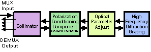
To achieve the narrow channel spacing and the desired performance, and to contain it within a compact package, the design team based the design on a high frequency holographic grating with free space optics. Each of the input beams (wavelengths) are directed onto a finely ruled grating at a precise angle so that they are reflected onto a common output fiber (see Figure 2).

The key to minimizing package size was creating a design that could use a high-frequency grating. Low frequency (less than 400 lines/mm) gratings can be used to achieve high diffraction efficiency—and low insertion loss—independent of the polarization condition of the laser light. However, the low dispersion of coarse gratings requires relatively long focal length focusing optics, which, in turn, increases the size of the package.
The diffraction efficiency of high frequency gratings is sensitive to the state of polarization of the incident light. To meet performance requirements for polarization-dependent loss, the device incorporates an optical component that converts the polarization of the beam incident on the diffraction grating to a specific polarization state. The beam passes through the device twice: once in an inbound direction and again in an outbound direction. The polarization-conditioning component enables mux/demux to achieve high diffraction efficiency, independent of the state of polarization of the input beam.
Optical design and packaging
Remaining beam path optics (see Figure 3) are designed around the high frequency grating to achieve the required performance. Specific requirements and characteristics for the optical design are:
- maintain beam quality for maximizing efficiency in coupling one or more beams into single-mode and multi-mode fibers to minimize insertion loss and cross talk;
- provide flexibility for assembling the device to any consecutive set of wavelengths in the ITU grid—one design covers wavelengths in the C and L bands; and
- minimize beam path length to minimize package size.

- The precision optical assembly is housed in a monolithic titanium package. In comparison with other materials, titanium offered advantageous mechanical and physical properties, including low weight, high stiffness-to-weight ratio, high durability, and compatibility with the coefficient of thermal expansion for optical glasses used. In addition, the material is easily machined. Once aligned for the correct wavelengths, the optical elements can be fixed to the package by laser welding to further stiffen the assembly.
Performance
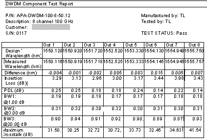
The grating based mux/demux is characterized by exceptionally good throughput, as measured by both insertion loss and polarization dependent loss, especially when compared to many of the technologies used to produce 8 channel, 100 GHz components (see Figure 4). The level of insertion loss demonstrated in the test results shown are achieved in the production of 16 channel devices, as well.

The difference between the measured and design (ITU grid) wavelength is better than ±0.03 nm. Bandwidth measurements (BW1, BW2, and BW3) give the width of the Gaussian shaped passband (transmitted power vs. wavelength) at the indicated levels below the peak. For example, the bandwidth at -1 dB (79% of the peak throughput) is 0.17 to 0.19 nm. Crosstalk, a measure of noise created by signals from other channels (adjacent and non-adjacent) being superimposed on the signal wavelength, is considerably better than the specification of 25 dB.
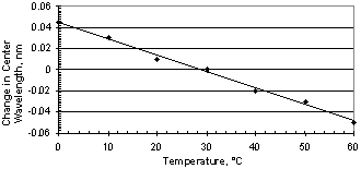
As shown in Figure 5, wavelength sensitivity without active temperature control is better than 2 pm/°C over a range from 0 to 60° C.

Platform design
The flexible design allows the same component to be used for both multiplexing and demultiplexing. This characteristic is attractive to network suppliers, since it contributes to reducing inventory.
As indicated earlier, one of the project goals was to create a design platform that would be the basis for new models (e.g. 200 GHz, 50 GHz), new capabilities, and new applications. The unit has demonstrated its capability for fixed and reconfigurable add/drop application and for modifying the selected multiplexed wavelength bands. This same platform has also been adapted to multi-mode fiber applications.
About the authors…
Tim Boord is principal investigator and Terry VanderWert is business manager of fiber optic products at APA Optics Inc. Terry VanderWert can be reached at APA Optics, 2950 North East 84th Lane, Blaine, MN 55449. Tel: 612-784-4995; Fax 612-784-2038; E-mail vanderwert@apaoptics.com.
